
FusionCoreEnIP
EtherNet/IP industrial I/O adapter stack for ESP32-P4
Status: This project is a proof-of-concept implementation and requires further development, testing, and validation before production use.
Overview
FusionCoreEnIP is a comprehensive EtherNet/IP adapter device built on the ESP32-P4 platform, providing industrial-grade connectivity for multiple sensors and I/O modules. The device integrates seamlessly with PLCs and industrial automation systems through standard EtherNet/IP protocols, while offering a modern web interface and REST API for configuration and monitoring.
This project combines roles from multiple projects into a single, modular platform: VL53L1X time-of-flight distance sensor, LSM6DS3 IMU, NAU7802 precision scale, MCP230XX GPIO expanders, GP8403 DAC modules, and more. All hardware components are optional and modular—you can configure the device to use none, some, or all of the supported hardware based on your application needs.
Hardware Platform
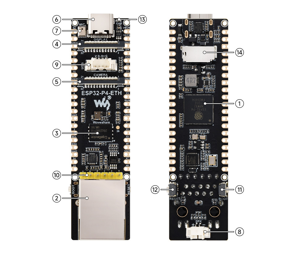
This project targets the Waveshare ESP32-P4 WiFi6 Dev Kit with the following specifications:
- Microcontroller: ESP32-P4 (Espressif)
- Development Board: Waveshare ESP32-P4 WiFi6 Dev Kit (used for development and testing)
- Ethernet PHY: IP101 (10/100 Mbps)
- Interface: I2C bus for sensor and I/O communication
- User LED: GPIO27 for status indication
- Flash: Partition-based firmware storage with OTA support
Supported Sensors and Input Devices
All supported devices have been validated and confirmed working:
- VL53L1X: Time-of-Flight Distance Sensor (max: 1 device)
- LSM6DS3: 6-DOF IMU (max: 1 device)
- NAU7802: 24-Bit Weight Scale ADC (max: 1 device)
Supported Output Devices
- MCP230XX: GPIO Expanders (max: 8 devices, addresses 0x20-0x27)
- GP8403: DAC (Digital-to-Analog Converter) (max: 4 devices, addresses 0x58-0x5B)
EtherNet/IP Protocol Support
Core Functionality
- OpENer EtherNet/IP Stack: Full-featured EtherNet/IP adapter implementation
- Input Assembly (100): 72-byte assembly containing sensor readings and device feedback
- Output Assembly (150): 40-byte assembly for controlling device outputs
- Explicit Messaging: Support for explicit (request/response) messaging
- Implicit I/O Messaging: Cyclic data exchange via Input/Output assemblies
- Connection Management: Multiple simultaneous connections
Connection Capabilities
- Up to 1 Exclusive Owner connection
- Up to 1 Input Only connection (with 3 connection paths)
- Up to 1 Listen Only connection (with 3 connection paths)
- Up to 6 explicit connections
- Maximum 20 simultaneous sessions
Implemented CIP Objects
The device implements comprehensive CIP object support:
- Identity Object (Class 0x01): Device identification and status
- Message Router Object (Class 0x02): CIP message routing and object discovery
- DeviceNet Object (Class 0x03): DeviceNet protocol support
- Assembly Object (Class 0x04): Input Assembly 100 and Output Assembly 150
- Connection Manager Object (Class 0x06): Connection establishment and management
- TCP/IP Interface Object (Class 0xF5): Network configuration with ACD support
- Ethernet Link Object (Class 0xF6): Ethernet interface status and statistics
- QoS Object (Class 0x48): Quality of Service configuration
- File Object (Class 0x37): EDS file and icon serving
- Parameter Object (Class 0x0F): Device configuration parameters (60 instances)
- Port Object (Class 0xF4): Communication port information
- LLDP Management Object (Class 0x109): LLDP configuration and control
- LLDP Data Table Object (Class 0x10A): LLDP neighbor information
LLDP Support
The device includes IEEE 802.1AB compliant Link Layer Discovery Protocol support:
- Automatic neighbor discovery and topology mapping
- CIP Identification TLV transmission in outgoing LLDP frames
- Neighbor information storage with CIP Identity data
- Configurable transmission intervals (default: 30 seconds)
- Configuration via EtherNet/IP CIP objects
Web Interface and REST API
The device provides a comprehensive web interface and REST API:
- Device Configuration: Network settings, sensor enable/disable, parameter configuration
- Real-time Monitoring: Sensor readings, device status, connection information
- Firmware Management: OTA firmware updates via web interface
- REST API: Programmatic access to all device functions
Assembly Data Layout
Input Assembly (Instance 100) - 72 Bytes
The input assembly contains sensor readings and device feedback:
- Bytes 0-3: VL53L1X distance data (4 bytes, uint32_t, little-endian)
- Bytes 4-19: LSM6DS3 IMU data (16 bytes: accel, gyro, roll, pitch)
- Bytes 20-27: NAU7802 scale data (8 bytes: weight, status)
- Bytes 28-59: MCP230XX input feedback (32 bytes, 8 devices × 4 bytes)
- Bytes 60-71: Reserved for future expansion
Output Assembly (Instance 150) - 40 Bytes
The output assembly contains control data for device outputs:
- Bytes 0-15: MCP230XX output control (16 bytes, 8 devices × 2 bytes)
- Bytes 16-31: GP8403 DAC output values (16 bytes, 4 devices × 4 bytes)
- Bytes 32-39: Reserved for future expansion
Software Stack
- ESP-IDF: Version 5.0 or later
- OpENer: EtherNet/IP stack
- lwIP: TCP/IP networking stack
- OTA: Over-the-air firmware updates
- NVS: Non-volatile storage for configuration
Modular Architecture
Important: Use of any specific hardware component is entirely optional. The modular component architecture makes it straightforward to add support for custom hardware by implementing additional components following the existing patterns. Additionally, any hardware supported by ESP32/ESP-IDF can be integrated with some development effort.