
QuinLED Penta Plus EtherNet/IP
EtherNet/IP controller firmware for the QuinLED Penta Plus (ESP32 + Ethernet)
Status: This project is a proof-of-concept implementation and requires further development, testing, and validation before production use.
Overview
A proof-of-concept port of the OpENer EtherNet/IP stack to ESP32 with Ethernet, targeting the QuinLED Penta Plus LED controller board. This implementation was developed to address a specific industrial automation requirement: an RGB stack light controller for a Motoman robotic manufacturing workcell.
The system enables direct integration of visual status indicators with the workcell's EtherNet/IP network infrastructure, allowing PLCs and other industrial control systems to programmatically control stack light colors and patterns for operator feedback and system status indication. The Motoman Robot can directly control the stack light through EtherNet/IP implicit messaging, providing real-time visual feedback synchronized with robot operations and workcell status.
Hardware Platform
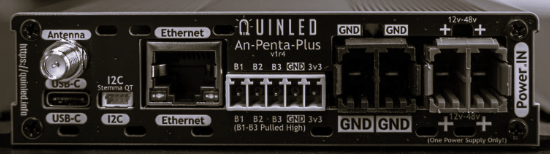
Target board: QuinLED Penta Plus (QuinLED.info). The QuinLED Penta Plus is an advanced ESP32-based LED controller board designed for professional lighting control applications.
- Microcontroller: ESP32-WROOM-32UE (Espressif, 4 MB Flash)
- Ethernet: LAN8720 PHY with RMII interface (PHY address 0)
- Ethernet Pins: MDC GPIO23, MDIO GPIO18, REF_CLK GPIO17
- Display: Optional SPI OLED
- I2C: External I2C connector (Stemma QT/Qwiic compatible)
LED Channels
The board provides comprehensive LED control capabilities:
- 5 Analog PWM Channels: Cool White (GPIO33), Warm White (GPIO32), Blue (GPIO12), Green (GPIO4), Red (GPIO2)
- 1 Digital LED Channel: WS2812/SK6812 compatible on GPIO5, relay control on GPIO13
- Digital LED Capacity: Up to 65,535 LEDs per strip
- PWM Configuration: 5 kHz frequency, 13-bit resolution (0–8191 steps)
Digital Inputs
Three digital inputs provide status feedback and control signals:
- Digital Input 1: GPIO36 (input-only, active-low)
- Digital Input 2: GPIO39 (input-only, active-low)
- Digital Input 3: GPIO34 (input-only, active-low)
Note: GPIO 34, 36, and 39 are input-only pins on ESP32 and cannot be configured as outputs. These pins do not support internal pull-up resistors, so external pull-ups are required (provided by the board hardware).
EtherNet/IP Assembly Structure
The device implements two EtherNet/IP assemblies for I/O data exchange:
Output Assembly (Instance 150)
11-byte output assembly used to send control data from the EtherNet/IP scanner (PLC) to the device:
| Byte | Offset | Description | Range |
|---|---|---|---|
| 0 | LED_OUTPUT_OFFSET_CW | Cool White LED brightness | 0–255 |
| 1 | LED_OUTPUT_OFFSET_WW | Warm White LED brightness | 0–255 |
| 2 | LED_OUTPUT_OFFSET_B | Blue LED brightness | 0–255 |
| 3 | LED_OUTPUT_OFFSET_G | Green LED brightness | 0–255 |
| 4 | LED_OUTPUT_OFFSET_R | Red LED brightness | 0–255 |
| 5 | LED_OUTPUT_OFFSET_DIGITAL_COUNT_LOW | Digital LED count (low byte) | 0–255 |
| 6 | LED_OUTPUT_OFFSET_DIGITAL_COUNT_HIGH | Digital LED count (high byte) | 0–255 |
| 7 | LED_OUTPUT_OFFSET_DIGITAL_ENABLE | Digital LED enable (0=off, 1=on) | 0–1 |
| 8 | LED_OUTPUT_OFFSET_DIGITAL_R | Digital LED red component | 0–255 |
| 9 | LED_OUTPUT_OFFSET_DIGITAL_G | Digital LED green component | 0–255 |
| 10 | LED_OUTPUT_OFFSET_DIGITAL_B | Digital LED blue component | 0–255 |
Implementation Notes:
- Bytes 0–4 control the 5 analog PWM LED channels (GPIO 33, 32, 12, 4, 2). These channels can be used independently or combined for color mixing.
- Bytes 5–6 form a 16-bit little-endian value for digital LED count (0–65,535 LEDs).
- Byte 7 enables/disables the digital LED output via relay control (GPIO 13).
- Bytes 8–10 are RGB color values for all digital LEDs (WS2812/SK6812 format, sent via GPIO 5).
Input Assembly (Instance 100)
14-byte input assembly used to send status data from the device back to the EtherNet/IP scanner:
| Byte | Offset | Description | Range |
|---|---|---|---|
| 0–10 | — | Mirrored from Output Assembly | Same as Output |
| 11 | INPUT_OFFSET_DIGITAL_INPUTS | Digital Input 1 state (0=low, 1=high) | 0–1 |
| 12 | INPUT_OFFSET_DIGITAL_INPUTS + 1 | Digital Input 2 state (0=low, 1=high) | 0–1 |
| 13 | INPUT_OFFSET_DIGITAL_INPUTS + 2 | Digital Input 3 state (0=low, 1=high) | 0–1 |
Implementation Notes:
- Bytes 0–10 mirror the current output assembly values, providing read-back of control values for verification and status monitoring.
- Bytes 11–13 report the state of the 3 digital inputs (GPIO 36, 39, 34). These inputs are active-low with pull-up resistors, so a GPIO low reading indicates an active input (value = 1).
EtherNet/IP Connection Types
The device supports three standard EtherNet/IP connection types:
- Exclusive Owner (Connection 1): Bidirectional I/O connection (Output 11 bytes, Input 14 bytes). Full control and status monitoring. Configurable RPI (Requested Packet Interval). Recommended for primary control applications.
- Input Only (Connection 2): Unidirectional input connection (Input 14 bytes only). Status monitoring without control capability. Configurable RPI. Useful for monitoring-only applications.
- Listen Only (Connection 3): Unidirectional multicast input connection (Input 14 bytes only). Read-only status monitoring. Configurable RPI. Suitable for passive monitoring and diagnostics.
Device Identity
The device presents the following identity information to EtherNet/IP scanners:
- Vendor ID: 55512 (AGSweeney Automation)
- Device Type: 7 (Generic Device)
- Product Code: 1
- Major Revision: 1
- Minor Revision: 1
- Product Name: "QuinLEDPentaPlus"
- Serial Number: 779240089
Network Configuration
The device supports both DHCP and static IP configuration:
- DHCP: Automatically obtains IP address, gateway, and DNS from network DHCP server
- Static IP: Manually configured IP address, netmask, gateway, and DNS servers
- Hostname: Configurable (default: "QuinLED-EnIP")
- NVS Storage: Network configuration is saved to NVS flash and persists across reboots
A minimal web interface is provided at http://<device-ip>/api/ipconfig for network configuration and diagnostics.
Software Stack
This project uses the following software components:
- ESP-IDF: Version 5.5.1 or later
- OpENer: Open-source EtherNet/IP stack for I/O adapter devices
- lwIP: Lightweight TCP/IP stack for embedded systems
- Web UI: Minimal HTTP interface for IP configuration
Disclaimer
This project is not affiliated with, endorsed by, or connected to QuinLED. QuinLED and QuinLED Penta Plus are trademarks of their respective owners. This project uses the QuinLED Penta Plus board as the target hardware platform for demonstration purposes only.