
Teknic ClearCore OpENer EIP
OpENer EtherNet/IP adapter on Teknic ClearCore (non-ESP platform)
Status: This project is a proof-of-concept implementation and requires further development, testing, and validation before production use.
Overview
This project provides an EtherNet/IP communication stack implementation for the Teknic ClearCore platform using OpENer (Open Source EtherNet/IP Communication Stack) and lwIP (Lightweight IP stack). This implementation ports OpENer version 2.3.0 to the ClearCore platform, enabling EtherNet/IP compliant I/O adapter functionality.
The device acts as an EtherNet/IP adapter, supporting both explicit messaging (for configuration and diagnostics) and implicit I/O connections (for real-time data exchange). This project demonstrates OpENer's portability to non-ESP platforms, specifically the Teknic ClearCore motion and I/O controller.
Hardware Platform
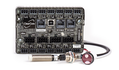
This project targets the Teknic ClearCore platform:
- Platform: Teknic ClearCore (non-ESP)
- Ethernet: 10/100 Mbps Ethernet interface
- SDK: ClearCore SDK (hardware abstraction layer)
- Development: C++ development environment
Software Stack
This project integrates the following components:
- OpENer: Open source EtherNet/IP stack for I/O adapter devices (version 2.3.0)
- lwIP: Lightweight TCP/IP stack for embedded systems
- ClearCore SDK: Teknic ClearCore hardware abstraction layer
EtherNet/IP Features
Core CIP Objects
- Identity Object: Device identification and status
- TCP/IP Interface Object: Network configuration (IP address, subnet mask, gateway)
- Ethernet Link Object: Physical layer status and statistics
- Connection Manager Object: Manages explicit and implicit connections
- Assembly Object: I/O data mapping
- QoS (Quality of Service) Object: Network quality of service configuration
Connection Capabilities
- Explicit Connections: 6 simultaneous explicit messaging sessions
- I/O Connections: 1 Exclusive Owner connection
- Input-Only Connection: 1 connection (with up to 3 connections per connection path)
- Listen-Only Connection: 1 connection (with up to 3 connections per connection path)
- Maximum Sessions: 20 supported encapsulation sessions
Disabled Features
- CIP File Object (disabled)
- CIP Security Objects (disabled)
- DLR (Device Level Ring) support (disabled)
Sample Application - Assembly Mappings
The sample application demonstrates a simple digital I/O mapping between EtherNet/IP assemblies and ClearCore hardware connectors.
Input Assembly (Instance 100)
The Input Assembly is a 32-byte data structure that maps to digital input connectors. Before each data transmission, the assembly is populated from hardware:
| Bit Position | ClearCore Connector | Description |
|---|---|---|
| Bit 0 | DI-6 | Digital Input 6 |
| Bit 1 | DI-7 | Digital Input 7 |
| Bit 2 | DI-8 | Digital Input 8 |
| Bit 3 | A-9 | Analog/Digital Input 9 |
| Bit 4 | A-10 | Analog/Digital Input 10 |
| Bit 5 | A-11 | Analog/Digital Input 11 |
| Bit 6 | A-12 | Analog/Digital Input 12 |
| Bits 7-255 | — | Reserved (unused) |
Hardware Initialization: DI-6, DI-7, DI-8, A-9, A-10, A-11, and A-12 are configured as digital inputs during application startup.
Output Assembly (Instance 150)
The Output Assembly is a 32-byte data structure that controls digital output connectors. When data is received from the EtherNet/IP scanner, the assembly data is processed and hardware outputs are updated:
| Bit Position | ClearCore Connector | Description |
|---|---|---|
| Bit 0 | IO-0 | Digital Output 0 |
| Bit 1 | IO-1 | Digital Output 1 |
| Bit 2 | IO-2 | Digital Output 2 |
| Bit 3 | IO-3 | Digital Output 3 |
| Bit 4 | IO-4 | Digital Output 4 |
| Bit 5 | IO-5 | Digital Output 5 |
| Bits 6-255 | — | Reserved (unused) |
Hardware Initialization: IO-0 through IO-5 are configured as digital outputs during application startup.
Data Flow: When output assembly data is received:
- The received data is copied to the input assembly (for read-back/mirroring)
- Individual bits are extracted and applied to the corresponding hardware outputs
- Each output connector state is set based on its corresponding bit value
Configuration Assembly (Instance 151)
A 10-byte configuration assembly is available for device-specific configuration parameters. Currently, this assembly accepts any configuration data but does not perform specific configuration actions in the sample application.
Connection Point Configuration
The sample application configures an Exclusive Owner connection point (connection point 0) that uses:
- Output Assembly: 150 (for data from scanner to device)
- Input Assembly: 100 (for data from device to scanner)
- Config Assembly: 151 (for configuration data)
Network Configuration
The device supports both DHCP and static IP configuration:
- Settable TCP/IP Interface: Network parameters can be configured via CIP messages
- Ethernet Link Counters: Statistics tracking enabled for network diagnostics
- DHCP Support: Automatic IP configuration with fallback to static IP (192.168.1.100)
Project Structure
Place this repository rooted in the same parent directory as libClearCore and LwIP to properly find include files and libraries:
- main.cpp: Main application entry point
- OpENer/: OpENer EtherNet/IP stack source
- lwip-master/: lwIP TCP/IP stack
Usage
The application initializes the Ethernet interface, configures network settings (via DHCP or static IP), and starts the OpENer stack. The main loop:
- Refreshes the Ethernet manager
- Calls
opener_cyclic()every 10ms for stack processing - Monitors connection status via LED indication
- Prints periodic status updates via USB serial
License
This project uses OpENer, which is licensed under the OpENer Open Source License (adapted BSD style). See OpENer/license.txt for details.